In this work, a new test rig is introduced to assess various head impact scenarios on different types of helmets. The test rig is a free-fall system where a helmeted headform is suspended instead of being placed on a basket frame and detaches from the system before the impact allowing an unrestricted motion. The proposed testbed showed to be effective in performing helmet impact tests at different angles. The test rig is particularly effective in tests at steep anvil angles, such as 15°, which could be problematic utilizing conventional test rigs with a basket frame. This is because, right before impacting the anvil, the helmeted headform is detached from the system enabling the helmeted headform to move freely during impact. In addition, the test results showed low CVs and high repeatability within the same impact scenario. The results showed that the proposed test rig could perform oblique impact tests on a wide range of angles without causing damage to the test rig. The results of the impact tests also suggest both the magnitude and duration of an impact are necessary for a more effective assessment of helmet performance.
Biomechanics, Impact testing, Helmet, Oblique impact, Helmet assessment, Head injury
Studies on the epidemiology of head injuries over the years have led to many advancements in the field of head protection. Helmets are mostly being designed and certified to minimize the risk of skull fractures, which have limited benefits for protecting against Traumatic Brain Injuries (TBI) and mild TBI [1-4]. Although current helmet certifications are mainly based on measuring the linear acceleration, many research studies have also linked TBI to the magnitude of rotation induced on the head due to significant shear strains exerted on brain tissues [5-8]. Rotational forces can increase the risk of TBI such as Diffuse Axonal Injuries (DAI), Subdural Hematomas (SDH), and concussions [9-12]. According to statistics, the number of reported concussion incidence has increased [2] and it is believed to be attributed to factors such as more awareness of head injuries, higher population, and living a more active lifestyle [13,14]. To better predict the risk of head injury, helmets should be evaluated for their ability to mitigate both linear and rotational accelerations of the head.
Whyte, et al. [15] provided a thorough review of the methodologies and conditions for impact testing of helmets. One of the most common methods of testing involves Anthropomorphic Test Dummy (ATD) headforms, striking a stationary impact opponent via a guided vertical drop. Drop testing equipment in some studies follows the direction of various helmet testing standards that suggest guided wires and monorail systems [16-21]. In those studies, helmeted headform is fixedly attached to the moving carriages, which only allows the head to move along a single axis. While this may be adequate for measuring linear acceleration, the rigid connection prevents the rotational motion of the headform.
As other researchers considered the effects of the human neck and torso within the context of impact testing, the use of neckforms was introduced into testing methodologies [3,22-25]. Instead of developing a suitable neckform for helmet testing, a Hybrid III neck that was already available for vehicle crash testing was broadly used in helmet impact testing. However, Hybrid III necks are too stiff and known to have characteristics unlike that of a human neck [26-30]. As a result, some helmet impact evaluation methods adopted custom neck surrogates to substitute the Hybrid III necks [26,31,32].
Aldman, et al. (1976) pioneered early studies of helmeted headform testing with a drop tower, which released an ATD head-neck assembly to fall freely onto a rotating disk platform. A horizontal velocity component is generated by the disk, which was prepared with various surface conditions, to emulate realistic accident scenarios wherein a helmet wearer strikes the ground head-first. Harrison, et al. (1996) had a similar approach to drop testing but with a deformable horizontally translating impact surface. This concept was further developed by Halldin, et al. (2001), wherein a detached helmeted headform was raised to a certain height via a monorail, and then dropped onto a gas-propelled steel plate [33]. An update to that design was applied where a Hybrid III headform was used, and an additional vertical rail reinforced the drop assembly [34]. Versions of the guided rail and moving horizontal surface format were later adopted using moving carriages with head-neck assemblies [22,35].
Before the development of Halldin's oblique impact testing method, studies on the impact literature review, reconstruction, and analysis of motorcycle accidents were conducted as part of the European research action [36]. The impact tests presented in the final report described a drop test rig that utilized a support ring surrounded with several adjustable thin rods which hold the helmeted headform at a desired orientation [37]. Subsequent methods using basket supports, and adjustable rods were fashioned for free fall impact tests on bicycle helmets [38-41].
In this study, we propose a new test rig for studying free fall oblique impacts for a helmeted headform. The test rig, Suspend-X, was designed and built at the Head Injury Prevention (HIP) Lab at Simon Fraser University (Surrey, BC, Canada). Suspend-X is a patent-pending test rig [42] that uses a suspending arm instead of a basket frame to hold a detached helmeted headform in place during the fall. For the purpose of this study, Suspend-X was used to perform drop tests at various angles on an American football helmet, to investigate the importance of the duration in addition to the magnitude of an impact.
The drop test towers are mostly used to subject a helmeted headform to a guided fall or free-fall via rail with the help of gravity. In the guided fall, the headform is fixed to the carriage using either a surrogate neckform or a solid attachment, which results in limited or no rotational acceleration of the headform.
On the other hand, the free-fall impact test rig allows the headform to freely rebound off the impacted anvil and generate both linear and rotational acceleration after impact. As shown in Figure 1, the helmeted headform is placed on a basket frame that is attached to the rail by a carriage. The basket frame allows the helmeted headform to maintain its position and orientation prior to impacting the anvil.
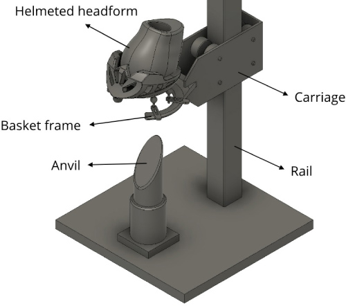 Figure 1: Drop tower with carriage installed with a basket frame to support a helmeted test headform.
View Figure 1
Figure 1: Drop tower with carriage installed with a basket frame to support a helmeted test headform.
View Figure 1
The basket frame, as shown in Figure 1, has a potential disadvantage when arranged for drop testing onto anvils with steep angles such as 15° to the vertical, as required in the ECE 22.05 oblique impact testing standard [43]. During such impacts, the helmeted headform may rebound off the anvil and strike the falling basket frame, leading to unintentional damage on the testing apparatus and headform, which in turn could affect the integrity of the system.
Another method used for evaluating headgear performance with the ATD headform is by generating momentum for both colliding objects, which are the helmeted headform and the anvil [22,34,35]. To create an impact scenario, both helmeted headform and the anvil require to have a certain speed and impact each other at a specific angle to generate the final required speed and angle of impact.
Other studies used a combination of a pendulum and a rail where the headform, fixed to the pendulum arm drops from certain heights to strike an oblique anvil [25,44]. The pendulum arm was devised to maintain a levelled headform that would strike perpendicular to the direction of the falling anvil. Testing with a moving plate can present different impact conditions from drop testing onto static anvils. Compared to a vertical drop onto a stationary surface, the horizontal striking plate could produce dissimilar head accelerations due to the different normal forces observed between the two scenarios [45]. By manipulating the speeds of the individual moving objects, the pendulum and plate methods can achieve high resultant impact speeds [25,34]. However, having more moving components adds to the complexity of the testing and causes repeatability and maintenance issues [34,35]. However, such methods can be valuable for reproducing real-life impacts for automotive or sports accidents.
During standard impact testing for football and ice hockey, a stationary ATD assembly is struck by a moving impactor mass [23,32,46-48]. Pellman, et al. (2006) and Jadischke, et al. (2016) performed testing with a pendulum arm, and a Hybrid III head-neck assembly mounted on a sliding base, which allowed up to five degrees of freedom after an impact. A similar method was used in the hockey impact study by Oeur, et al. (2014), where the impacting mass was rapidly pushed by a pneumatic linear ram towards an ATD assembly.
Testing by linear impactors such as a pneumatic linear ram and a pendulum arm simulates a helmet-to-helmet impact [46], however, it produces little tangential force [45]. Research studies showed that the tangential force is a key contributor to the rotational acceleration of the head [49,50]. Furthermore, it is known that injuries can also occur due to impacting against playing surface, body parts, and jersey [51-53], which may not be accurately represented by testing with a linear impactor.
The purpose of using a sliding base in linear impactor tests is to allow movement of a struck object after an impact, as seen in real-life collisions. Pellman, et al. [46] showed that rigidly attaching a head-neck assembly to the base sliding results in excessive loading and does not produce the same impact response as in accident reconstruction. In addition, Walsh, et al. [54] utilized the translating table to simulate torso mass and found no significant difference in linear and rotational responses between rigidly affixing the lower neck of the head-neck assembly versus mounting the lower neck to a 12.78 kg translating table. A study by Beusenberg, et al. [55] suggested that the effect of changing torso mass was minimal on the head kinematics.
The Hybrid III neckform is commonly used in helmet testing studies despite being too stiff and resulting in high resistance to horizontal and translational motion between the head and body [15,28,29,34]. Hybrid III neckform was originally designed for car crash testing [15,56] and its behaviour is only known for flexion and extension. For other types of motion, such as lateral, the behaviour of the Hybrid III neckform has not been studied [27,30,57].
A study by Nightingale, et al. (1996) suggested a minimum influence of the neck on the head kinematics for the first 9 ms of impact due to a mechanical separation between the head and neck [58]. Ono, et al. (2003) showed negligible neck muscle activity for the first 50 ms or 80 ms of an impact, depending on the impact being anticipated or not [59]. A similar study by Kuramochi, et al. (2004) showed that the muscles of the neck require 13-14 ms to respond to mild impact [60]. Furthermore, there is an atlanto-occipital neutral zone where the neck joint can have motion in the range of 10° without inducing any force that can affect the kinematics of the head [61,62]. Testing at the HIP Lab, including the ones performed in this study, showed that the rotational displacements of the head during the oblique impacts for the first 10 ms of the impact are less than 10°. In addition, most impact scenarios for helmet testing occur in a period between 7-15 ms, depending on the type of helmet, speed of impact, and contacting surface [1,63]. As a result, using a detached headform and a free-fall test rig can more accurately represent the head during an oblique impact compared to the Hybrid III neckform.
Following the concept of a free-falling helmeted headform, an alternative approach was taken for oblique impact testing. The main goal of this design is to enable a helmeted headform to freely move during impact and eliminate the need for the basket frame. This is achieved by introducing an arm that the helmeted headform is suspended from. Like the conventional test rigs, Suspend-X comprises a rail, a carriage, and an anvil, as shown in Figure 2a. The main difference between a conventional test rig for oblique impact and Suspend-X is the fact that the basket frame is replaced by a drop assembly that suspends the helmeted headform. The drop assembly is secured to the carriage and consists of a horizontal suspension arm, a vertical bar, and a release mechanism, also shown in Figure 2a. The helmeted headform is suspended on the release mechanism via cords. The cords were attached to different locations of the headform to allow the helmeted headform to have a given configuration. Small hook-and-loop fasteners are placed on different locations on the drop assembly as stabilizing points to preserve the suspending configuration. A gate is placed on the rail to trigger the release mechanism and disengage the cords and allow the helmeted headform to start its free-fall motion right before contacting the anvil. The Suspend-X was built at the HIP lab, as shown in Figure 2b.
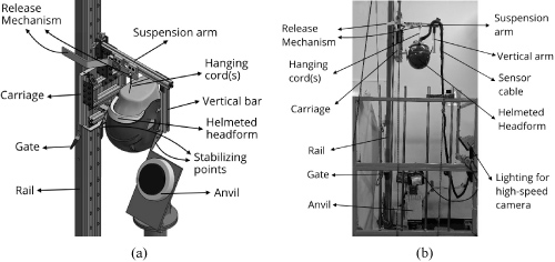 Figure 2: (a) Suspend-X, a novel oblique impact test rig; (b) Suspend-X built at the HIP lab.
View Figure 2
Figure 2: (a) Suspend-X, a novel oblique impact test rig; (b) Suspend-X built at the HIP lab.
View Figure 2
Oblique impacts were performed for different impact scenarios to demonstrate the use of the test rig. The tests also provide insight into the relationship between the angle of impact and the head response. For the purpose of this study, five tests were completed for each angle configuration, and the Coefficient of Variation (CV) was used to monitor the standard deviation of the results compared to the mean value.
Hybrid III headform is widely used in impact testing and is equipped with a removable synthetic skin with a 10 mm average thickness. Studies have shown that surface conditions between the helmet and the headform can influence the response of the headform during impacts [64,65]. Suspend-X can use any other headform such as metal headform, wooden headform, and NOCSAE headform. For the purpose of this study, a Hybrid III 50th percentile adult male headform is used.
The Hybrid III headform was fitted with a Riddell Speed football helmet (size Large). Football helmets were chosen specifically for their resilience in a repeated drop test. All tests were performed without the facemask or any other accessories. For each angle configuration, the helmeted headform was oriented to produce an impact at the frontal region of the helmet, as shown in Figure 3. This orientation corresponds to one of the most frequently impacted locations based on the impact studies for football [66-68]. Inside the headform, nine single-axis linear accelerometers (ENDEVCO 7204C) were embedded in a 3-2-2-2 array to determine linear and rotational acceleration based on the methods presented by Padgaonkar, et al. [69]. The rotational velocity was obtained through the integration of the rotational acceleration data. The rotational displacement was calculated by performing double integration of the rotational acceleration data from zero to 10 ms, starting when the pulse rises.
 Figure 3: Location of impact on the Riddell Speed helmet.
View Figure 3
Figure 3: Location of impact on the Riddell Speed helmet.
View Figure 3
The headform was dropped from a height allowing it to reach a nominal speed of 5.5 m/s prior to impacting a 42 Shore A Modular Elastomer Programmer (MEP) pad according to National Operating Committee on Standards for Athletic Equipment (NOCSAE) standard for newly manufactured football helmets [17]. Impact speed was measured using a photoelectric time gate installed adjacent to the guided rail. The anvil was inclined at three angles: 15°, 30°, and 45° to the vertical. A high-speed camera (Edgertronics SC2+) recorded impacts at 4,000 frames per second in high definition to monitor each trial. In each trial, the data collection and video recording sequence were initiated when the drop carriage passed through the first photoelectric sensor. Data from the accelerometers installed in the headform were recorded with a Data Acquisition (DAQ) system (National Instrument) at a 20-kHz sampling rate. LabVIEW software was used to manage the collection and data processing. Measurements from the accelerometers were filtered with a standard fourth-pole Butterworth 1000-Hz low-pass filter following the guidelines set in SAE J211 [70,71].
The results of drop tests with Suspend-X on to an oblique anvil inclined at three distinct angles showed in Table 1. For each impact scenario, the tests were repeated five times. When angled at 15°, the helmeted headform experienced an average peak linear acceleration of 44.74 g, rotational acceleration of 4.69 krad/s2, and rotational velocity of 36.63 rad/s. At 30°, the average peak linear acceleration was 82.10 g, rotational acceleration was 5.36 krad/s2, and rotational velocity was 36.10 rad/s. At 45°, the helmeted headform experienced an average peak linear acceleration of 96.40 g, rotational acceleration of 4.96 krad/s2, and rotational velocity of 31.38 rad/s.
Table 1: The average response of a detached Hybrid III struck at the FY region with varying angles (List of abbreviations: Accel.: Acceleration; Ave.: Average; CV: Coefficient of Variation; Lin.: Linear; No.: Number; Rot.: Rotational; Vel.: Velocity; Disp.: Displacement). View Table 1
As shown in Table 1, by increasing the anvil angle from 15° to 30°, the linear acceleration increases by 83.5% and a further increase to 45° resulted in a 17.4% increase compared to 30°. An increase in the angle from 15° to 30° resulted in an increase in the rotational acceleration by 14.2%. When the angle was increased from 30° to 45°, the tests resulted in an average of 7.4% decrease in rotational acceleration. Compared to tests with a 15° anvil, tests with a 30° resulted in 1.5% lower rotational velocity. The rotational velocity decreased further by 14.3% when dropping onto a more gradual sloped surface at 45° compared to 30°. The results showed that increasing the angle of impact from 15° to 45° increased the linear acceleration and decreased rotational velocity. However, rotational acceleration does not follow the same pattern as it increased as the angle of impact was increased from 15o to 30° and decreased from 30° to 45°. Sample graphs of each type of impact for linear acceleration, rotational acceleration, and rotational velocity are shown in Figure 4a, Figure 4b, Figure 4c, respectively. With an increase in the anvil angle from 15° to 30°, the linear and rotational acceleration responses mainly became higher in magnitude and shorter in duration while the rotational velocity decreased. Furthermore, increasing the anvil angle from 30° to 45° resulted in another increase in peak linear acceleration and a decrease in peak rotational acceleration and rotational velocity.
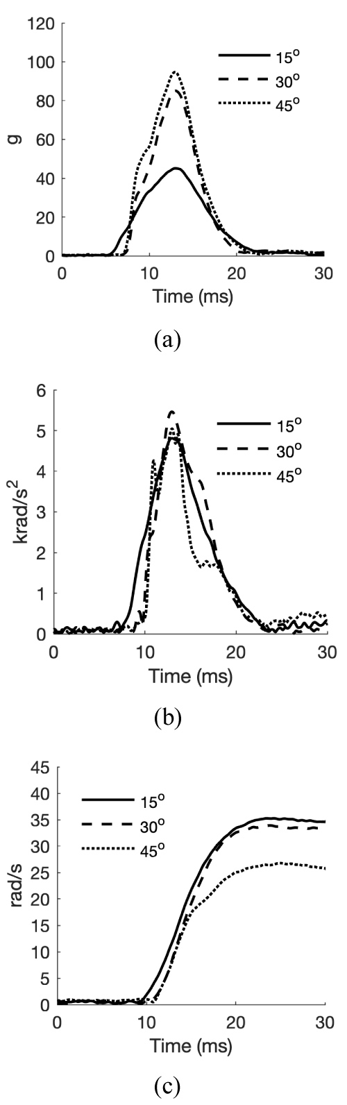 Figure 4: Plotting impact duration versus (a) linear acceleration; (b) rotational acceleration, (c) rotational velocity.
View Figure 4
Figure 4: Plotting impact duration versus (a) linear acceleration; (b) rotational acceleration, (c) rotational velocity.
View Figure 4
Research studies have shown that kinematic parameters of the head, such as linear acceleration, rotational acceleration, and rotational velocity, are closely linked to the risk and severity of the head injury [5,72-80]. The human brain can tolerate a relatively high magnitude of acceleration in a short period of time. However, when the period of acceleration becomes longer, the same impact magnitude can cause extensive damage to the brain [63,75]. Therefore, to determine the severity of an impact, having information about the magnitude and duration of the acceleration is paramount, and a helmet evaluation criterion requires to consider both factors in rating a helmet performance.
A new suspension-based oblique impact test rig for testing helmets was introduced. The test rig is a free-fall system where a helmeted headform is suspended instead of being placed on a basket frame and detaches from the system before the impact allowing an unrestricted motion. Suspend-X showed to be effective in performing helmet impact tests at different angles. In addition, the test results showed low CVs and high repeatability within the same impact scenario. The results showed that the proposed test rig can perform oblique impact tests on a wide range of angles without causing damage to the test rig. The results of the impact tests performed with Suspend-X showed that studying both the magnitude and duration of an impact test is necessary to evaluate a helmet performance.
This work was supported in part by grants from MITACS (10-11-4005-JJ) and the Natural Sciences and Engineering Council of Canada (PJ/421433/2011).