Introduction: Electrical shock is dangerous event, which can occasionally happen when we are exposed to any of alive conducting materials. Every year people are died or seriously injured by electrical accidents since electric current is not detected. There are two kinds of danger: one from electrical shock and the other caused indirectly by electrical fires.
Several factors in the operating room place the patient at unusual risk for electrocution. The patient is unclothed and frequently wet. The patient is on a large metal table, frequently electrically operated, to which he or she may be connected by large wet towels. The patient is surrounded by electrical devices, and is directly connected to several of them. These electrical devices are exposed to spilled fluids and operator abuses that increase the potential for short circuits. Moreover, the anesthetized patient is unable to respond to or withdraw from an electric shock.
General Safety Recommendations: The operation theatre must be set up so electrical cords; cables and equipment are protected from damage (including damage by liquids).
Staff and students must be educated to inspect for and immediately report any physical damage to electrical cords and appliances with the programmed incident reports.
All defective equipment should be removed from service immediately, and need to be labelled accordingly.
Electrical safety, Operation theatre, Monitoring equipment
Several factors in the operating room place the patient at unusual risk for electrocution. The patient is unclothed and frequently wet. The patient is on a large metal table, frequently electrically operated, to which he or she may be connected by large wet towels. The patient is surrounded by electrical devices, and is directly connected to several of them. The patient environment including anesthesia machine circuits is a prime target for electrical accidents. Nowhere else can one find these elements in other working areas: Lowered body resistance, more electrical equipment, and conductors such as blood, urine, saline, and water around the area. These electrical devices are exposed to spilled fluids and operator abuses that increase the potential for short circuits. Moreover, the anesthetized patient is unable to respond to or withdraw from an electric shock [1].
To review and discuss on medical equipment safety symbols and their implications on the three types of electrical currents which warrant separate discussions: macroshock, microshock, and radiofrequency (Bovie) currents (electrocautery devices) within the operating theater.
Electrical shock is dangerous event, which can occasionally happen when we are exposed to any of alive conducting materials. Every year people are died or seriously injured by electrical accidents since electric current is not detected [2]. There are two kinds of danger: one from electrical shock and the other caused indirectly by electrical fires. The danger of electrocution is often not recognized because of our familiarity with electrical equipment. Even in our homes, there is adequate electrical energy at any socket or outlet to let kill of several people at once. In the operation theatre, although the voltage is the same as that at home, the amount of current is many times that available in a home outlet. This increases both the danger from shock and the danger of electrical fire [1].
As different papers I reviewed report that every year people are killed or seriously injured by electrical accidents. There are two kinds of danger: that from electrical shock and that caused indirectly by electrical fires. The danger of electrocution is often ignored because of our familiarity with electrical equipment. Even in our homes, there is enough electrical energy at any socket or outlet to kill several people at once. In the theatre, although the voltage is the same as that at home, the amount of current can be many times that available in a home outlet. This increases both the danger from shock and the danger of electrical fire [3].
In order to ensure quality of patient care and reach productivity targets to an increasing extent level, hospital physical plants are, structured around technical hubs. This provides greater dependability, best quality and enhanced flexibility. Additionally, there are also classifications safety symbols that tell us about the nature of protection against electric shock a device has. The classifications, along with their symbols and their implications were discussed [4].
Electrical currents flow in circuits. In the case of a patient, a path must exist from the electrical source to the patient, and another path must exist from the patient back to the electric source, for a shock hazard to exist. The current, "I", is measured in amperes. For a current to flow through a conductor there must be a voltage difference, "V", from one end of the conductor to the other. Finally, every conductor, except for certain supercooled metals, offers resistance, "R", to the flow of current [5].
Mains electricity is usually supplied as an alternating current, which oscillates at a frequency of 50 Hz. It travels from the substation to its destination in two conductors – the live and the neutral wire [6].
The relationship between current, voltage, and resistance is expressed in Ohm's law: V=I * R. This is the same relationship as between cardiac output (current), mean arterial pressure minus central venous pressure (voltage), and systemic vascular resistance: (MAP - CVP) * 80 = C.O. * SVR. Usually, Ohm's law for the circulation is rearranged to solve for SVR. In considering electrical safety, we are mostly interested in solving for current flow through the patient: I = V/R [7].
• The size of any current is determined by two factors
(Ohms law): Current = Voltage / Resistance
Therefore Electricity can damage the body by mechanisms of electrocution, burns or ignition of a flammable material.
The Damage is dependent upon the intensity, type and duration of current. Current even as small as 50 μA can probably cause ventricular fibrillation (microshock) [8].
Patients must never be in direct contact with mother earth because for the shock to happen there must be a pathway from the source of current to the body and conducting a return pathway back to the source (complete circuit) as illustrated in the following figure 1 (source www.equipmentexplained.com ) [9].
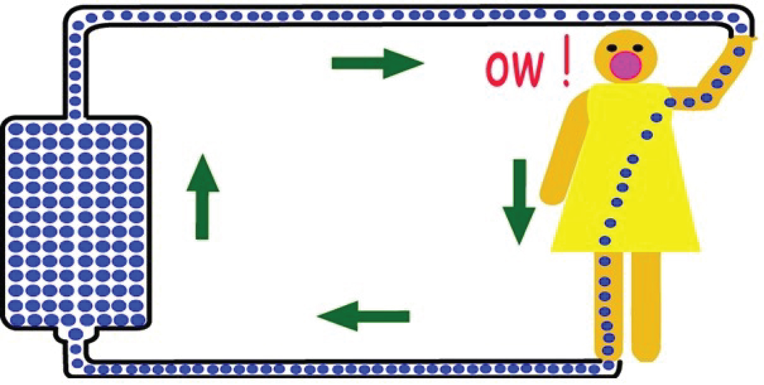 Figure 1: Source (www.equipmentexplained.com)
View Figure 1
Figure 1: Source (www.equipmentexplained.com)
View Figure 1
High resistance or non-conductors like rubber shoe will limit current flow (e.g between the electrical components of a piece of equipment and its box)
But low resistance connection to an earth terminal will limit charge build-up on equipment and limit problems of capacitance or storage [5].
So, the earth wire/ grounding/ (wire from equipment casing to mother earth) has vital as it prevents shock by:
a) Diverting current, and
b) Stopping the current flow by triggering mechanisems using devices. That stops high current flow (e.g. breakers; fuses, circuit breakers) [6].
Equipment design and Safety of Medical Equipment Figure 2 (sourcewww.equipmentexplained.com).
 Figure 2: Equipment design and Safety of Medical
Equipment (source www.equipmentexplained.com)
View Figure 2
Any conducting part of Class I equipment available to the user, such as the metal casing, is let connected to mother earth by an earth wire. This wire will be the third pin of the plug connecting the equipment to the mains socket.
• Equipment in this class makes use of the wire from equipment case to mother earth to provide adequate protection [10].
Any accessible conducting parts of Class II equipment are protected from the live supply by either double or re-inforced insulation. This should prevent any possibility of an accessible part becoming live and so an earth wire is not important.
• Equipment depends on at least different layers of insulation to provide adequate protection [10].
Class III equipment provides protection against electric shock by using voltages no higher than safety extra low voltage (SELV). SELV is defined as a voltage of not > 25 V AC or 60 V DC. In practice, these equipments are either battery operated or supplied by a SELV transformer. These equipments use low voltages provided by batteries or special power supplies to be "safe" [11].
This classification describes how much shock current flow is allowed to come into contact with the patient or operator if a fault occurred. Type B protection allows the most amount of shock current not to happen and the type CF is the strictest, allowing very little shock current to happen, type B (Body) protection, For example can be, the metal surface cover of the anesthetic machine may have this level of protection [11].
As for type B, but uses an isolated (or floating) circuit. In these type BF (Body Floating) protection are like, ports where a pulse oximetery probe would normally be connected to.
Type CF (Cardiac Floating) protection, a plug socket where one would plug in a central venous pressure (CVP) monitor attached this plug has the best level of protection. These provide the best degree of protection, using isolated circuits and having a maximum leakage current of < 10 A. They are suitable for direct cardiac connection, e.g. ECG leads, pressure transducers, conductors and thermo dilution computers [11].
Figure 3. (source Www. How equipment works.com).
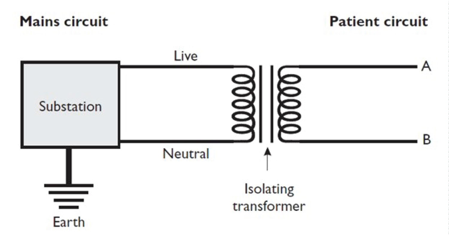 Figure 3: Source (www.howequipmentworks.com)
View Figure 3
Figure 3: Source (www.howequipmentworks.com)
View Figure 3
Isolated or floating circuits, provide a circuit whereby a connection between the electrical source and earth does not allow current to flow [9].
The relationship between current, voltage, and resistance is expressed in Ohm's law: V=I * R. This is the same relationship as between cardiac output (current), mean arterial pressure minus central venous pressure (voltage), and systemic vascular resistance: (MAP - CVP) * 80 = C.O. * SVR. Usually, Ohm's law for the circulation is rearranged to solve for SVR. In considering electrical safety, we are mostly interested in solving for current flow through the patient: [9]
I = V/R.
Current density is the amount of current flowing per unit area. There are situations in which a fairly small current can cause burns or arrhythmias because the current density is large (e.g. the current is delivered to a small area of tissue).
Macroshock has the potential for both burns and cardiac arrhythmias. Currents pass through the extremities mostly through the muscles. A current flowing from arm to arm, or arm to leg, must pass through the thorax. In the thorax the current is split between the chest wall and the great vessels, which obviously deliver the current directly to the myocardium [6].
How much current can we deliver to the anesthetized patient? In the case of a direct contact with line voltage, a patient may receive 150 volts. The current he can receive therefore depends on the resistance to flow (I=V/R) [6].
The main resistance to flow of current is the skin. The resistance of dry skin is about 50,000 ohms. The current through dry skin is therefore 150V / 50,000 ohms, which is .003 A, or 3 mA (milliamps). The current required for producing ventricular fibrillation across an arm-arm or arm-leg circuit is 80mA. Thus, a 3 mA current might cause a localized burn, but could not deliver a high enough current density to the myocardium to cause fibrillation. The resistance of wet skin is 1/100th that of dry skin, about 500-1000 ohms. This is also about the resistance of EKG electrodes [6].
The current that could be delivered is therefore 150V / 500 ohms, which is 300mA. This is well above the 80 mA threshold for ventricular fibrillation [5].
If either the ground wire or neutral wire breaks, then the entire 10 amp current will flow through the other wire. The chassis voltage will rise to 640mV. This is not enough to cause macroshock, (we previously calculated that 40 volts [40,000mV] was required) but, as we will see below, is well above the threshold required for microshock [5].
There are several obvious steps to prevent macroshock in the O.R. Equipment must be designed so the hot wire cannot easily short out with the chassis. Every chassis must be grounded. The ground wires must be regularly inspected, because a failed ground wire will permit the chassis to come up to full line voltage unnoticed. Finally, patients should not be connected to potential grounds, or to monitoring equipment which provides a direct connection to ground [10].
One of the best ways of preventing macroshocks, however, is the line isolation transformer as seen from the symbol figures above.
The twitch monitor like nerve stimulatrers in our OR poses a modest macroshock hazard. Good twitch monitors can produce 75mA of current, which is very near the documented threshold of 80mA known to produce fibrillation across an arm-arm or arm-leg circuit in adults. Since the current density will be increased in smaller patients, this may be above the fibrillation threshold in children [10].
Microshock refers to currents delivered directly to the myocardium via intracardiac electrodes or catheters. Because the current is delivered to a very small area, only a very small current is required to reach the fibrillation threshold. The currently accepted minimum current is 10 μA (microamps = 1/1000 of milliamps which we were discussing above) [8].
The intracardiac lead represents only half of the circuit. The current must travel through the patient to return to its source. The resistance of this circuit is therefore the patent's resistance plus the electrode's resistance. The patient's resistance to flow will be about 500 ohms. The voltage required to generate 10 μA through a 500 ohm circuit is 5mV (500 ohms * 10 μA [0.01 mA]) [8].
The following table 1 may help to compare the voltages required for macroshock currents and microshock.
Table 1: The following table may help to compare the voltages required for macroshock currents and microshock currents: [1] View Table 1
As the above discussion of neutral ground power systems it was noted that if the neutral wire connects with the grounded chassis on a device requiring 10 amps of current, this would raise the chassis to 320mV. If either the ground wire or the neutral wire should break, the chassis voltage would rise to 640mV. This small voltage would hardly be noticed to the touch, yet it is above the fibrillation threshold for saline intracardiac catheters and two orders of magnitude above the fibrillation threshold when pacing electrodes are in the heart, even though the ground wire is functioning properly! [4].
The point is this: It takes two shorts to the chassis of two devices, with both ground wires broken, for an undetected macroshock hazard to exist when using a line isolation transformer. However, a single short to the chassis of a device with a broken ground, or an internal short in a device lacking an isolated power supply, can create an undetected microshock hazard [6].
If ground wires are working, and all devices which are electrically connected to the patient have isolated power supplies, then the line isolation transformer will provide protection against both macroshock and microshock. If devices do not have isolated power supplies, then the transformer and monitor cannot guarantee a microshock hazard does not exist.
As mentioned above, microshock requires that the current be delivered to a very small area of the myocardium in order to reach high current density. CVP catheters, unless they float into the right ventricle, pose minimal microshock hazards.
Frequencies of 500,000 to 2,000,000 Hz are used by electrocautery ("Bovie") units. And the major concern about the use of electrocautery is burn prevention [2].
The current is returned to the electrocautery machine by the "grounding plate." This grounding plate does not ground the patient to the ground. As discussed above, patients should not be grounded! Although called the ground plate, it is merely the return electrode to the electrocautery unit.
The patient does not get burned at the grounding plate because the plate covers a very large surface; hence the current density at the plate is low.
The grounding plate may have a broken wire between it and the electrocautery unit. In this case, the current will find alternate routes back to the electrocautery unit [3].
The most likely other conductors are EKG electrodes. If an older EKG is being used in which the neutral (green) electrode is attached to ground, then the current can find its way back to the unit through this electrode. Concentrating the current at the site of the neutral EKG electrode has been responsible for numerous burns [6].
Any other conductor that the patient may be in contact with, such as the table, iv. Poles or stands, the monitor screen, wet covers etc., may serve as a potential route for the bovie current to pass back to the electrocautery unit. If this happens, there will be a high current density at the point where the patient is in contact with the conductor, and the potential for burn [2].
Recommended procedures for electrical safety should include the following points: [5]
• Use of isolated system (IT earthing)
• Reassure of proper grounding of the installation
• Continuous monitoring of isolation adequate insulaitions.
The operation theatre must be set up so electrical cords; cables and equipment are protected from damage (including damage by liquids). Staff and students must be educated to inspect for and immediately report any physical damage to electrical cords and appliances with the programmed incident reports.
The use of safety switches may be required in certain situations. Safety switches and portable safety switches must be tested at prescribed intervals by a competent person and removed from use if not working properly. The competent person must check that safety switches are only used when the inbuilt test button trips immediately and that the remained current trip is no more than 10mA, 40ms (Type 1 safety switch) or 30mA, 300ms (Type 2 safety switch) [11].
All defective equipment should be removed from service immediately, and need to be labeled accordingly.
Double adaptors and piggyback plugs are not let to be used. The only exception is attachment of theatrical equipment such as lighting and audio.
There are two major hazards from electrical appliances in the operating room: burns and arrhythmias. As mentioned above electricity can be dangerous that, which can occasionally happen when we are exposed to any of alive conducting wires, especially in the operating room, because there is so much electrical equipment around, anaesthetized patients cannot move away from danger, electric current is invisible, and there are fluids everywhere which can increase the risk of shock, to get a shock, the person must be part of a circuit including the earthed wire from central supply. The basic shock pathways diagram on page 2 helps us to understand this.
Insulation (of three types) can prevent shock, the earth wire (wire from equipment casing to mother earth) prevents shock by a) diverting current b) stopping the current flow by triggering devices that stop high current flow (e.g. fuses, circuit breakers). As indicated from the above discussion electric shock is classified as macro shock, micro shock or from radiofrequency (Bovie) currents. If the patient is at high risk of developing micro shock (e.g. when using cardiac pacemaker wires or central venous catheter monitoring), equipment designed to protect micro shock should be used.
Isolation transformers are also used to protect a person by isolating one part of the circuit from another by forming a gap. The isolation transformer does not have a wire from neutral to mother earth (earthling), and therefore does not provide a path for shock current to back through and forming a circle.
Lastly, electrocautery devices are common sources of ignition of fires in the operating room. The fuel for fires are readily available in the operating room, and include alcohol based prep solutions, bowel gas, and drapes. Clearly, the most important aspect of electrocautery is to be certain that the ground plate is properly positioned, and that the wires are intact between the plate and the electrocautery unit. Although electrocautery units have built-in safeguards to make certain the plate is functioning, they may not work.